
When it comes to electronics and electrical circuits, capacitors play a crucial role in storing and releasing electrical energy. However, just like any other component, capacitors can wear out or fail over time. To ensure your circuits operate smoothly, it’s essential to know how to test a capacitor effectively. In this article, we’ll explore signs of a bad capacitor, how to test capacitor, from using a multimeter or ESR to checking them in-circuit. So, let’s dive in and uncover the secrets of capacitor testing.
What is Capacitor
Capacitor is a device used to store energy electrostatically in an Electric Field. It is a passive two-terminal electrical component. The Capacitor is made of two close conductors or plates that are separated by a dielectric material. The plates store electric charge when connected to a power source.

Read More about Capacitors:
Capacitor Theory
How Capacitor Works
Capacitor charging and discharging cycle
Capacitor Number Marking – How to Decode with Example
How to Read Capacitor Color Marking Values
Different Type of Capacitors in Market with Description – Part I
Different Capacitor Types in Market with Description – Part II
Electrolytic Capacitor – Properties, Uses, Capacitance Value and Polarity
Ceramic Capacitor – Composition, Types, Properties and Applications
What is Supercapacitor (Ultracapacitor) – Characteristics, Working, Types
Why We Need to Test Capacitors
Before we delve into the testing methods, let’s understand why it’s crucial to check the health of capacitors. Imagine you’re working on a project, and your circuit isn’t behaving as expected. It could be due to a faulty capacitor. Testing capacitors helps you:
1. Ensure Proper Functionality
Testing capacitors ensures that they are working as intended. Faulty capacitors can lead to erratic circuit behavior or complete failure.
2. Prevent Component Damage
A defective capacitor can harm other components in your circuit. Identifying and replacing a bad capacitor can prevent further damage.
3. Save Time and Money
Replacing capacitors unnecessarily can be expensive and time-consuming. Testing helps you pinpoint the problem accurately.
When to Confirm if a Capacitor is Bad?
Testing a capacitor is not just about knowing the methods; it’s also about interpreting the results. A capacitor can be considered bad if it exhibits:
- Significantly Altered Capacitance: A drastic difference between the measured capacitance and the rated value indicates a problem.
- Leakage Current: A high leakage current suggests that the dielectric inside the capacitor may have deteriorated.
- Visual Anomalies: If you spot physical damage, leakage, or bulging, it’s a clear sign of a bad capacitor.
How to Test a Capacitor – Step by Step Methods
Like all electrical devices, a Capacitor is also sensitive to spikes. Such voltage swings can damage the Capacitors. Therefore, it is necessary to test the Capacitors regularly by following any of the methods given below. Different types of Capacitors are shown in Fig. 2.

Now that you understand the importance of capacitor testing, let’s explore different methods you can use:
- Multimeter Test for Capacitors
- Capacitor Testing by Measuring the Time Constant
- Capacitor Testing with Simple Voltmeter
- Capacitor Testing using Analog Multimeter
- ESR (Equivalent Series Resistance) Measurement
- Capacitor Testing by Shorting the Leads
Multimeter Test for Capacitors
One of the most common ways to test a capacitor is by using a multimeter. We can do this test in two different ways:
- Capacitor Testing using Multimeter with Capacitance Setting
- Capacitor Testing using Multimeter without Capacitance Setting
Test Capacitors using Multimeter with Capacitance Setting
Using a multimeter to test a capacitor is straightforward:
-
- Set your multimeter to the capacitance (usually labeled as “C”) mode.
- Discharge the capacitor by short-circuiting its terminals with a resistor or insulated screwdriver.
- Connect the multimeter probes to the capacitor terminals, ensuring the correct polarity.
- The multimeter will display the capacitance value. Compare it to the labeled capacitance. A significant deviation indicates a bad capacitor. It will display OL if the capacitance value is higher than the measurement range or the capacitor is faulty.

Note:Â Some multimeters offer a Relative (REL) mode. When measuring low capacitance values, the Relative mode can be used to remove the capacitance of the test leads. To place a multimeter in Relative mode for capacitance, leave the test leads open and press the REL button. This removes the residual capacitance value of the test leads.
Test Capacitors using Multimeter without Capacitance Setting
- At first, the Capacitor must be disconnected from the circuit board and then it should be discharged completely.
- Then, the knob of the Multimeter must be set to Ohm or Resistance Settings. In case of multiple ranges of resistance measurement, a higher range (usually 20 KΩ to 200 KΩ) should be selected.
- Next, the Multimeter probes must be connected to the terminals of the Capacitor. In case of an Electrolytic Capacitor, the red probe must be connected to the positive terminal of the capacitor and the black probe must be connected to the negative terminal of the Capacitor. In case of Non-Electrolytic Capacitor, it can be connected in either way.
- After that, a reading of resistance will be shown on the display by the Digital Multimeter. It will then display the resistance of an open circuit (i.e. infinity). The reading for that short period should be noted down.
- Then, the Capacitor must be disconnected from the Multimeter and the test must be repeated several times.
- For a good Capacitor, every attempt of the test should show a similar result on the display. If in the further tests there is no change in the resistance, then the capacitor should be replaced as it is a dead one.
Test Capacitors by Measuring the Time Constant
- At first, the Capacitor must be disconnected from the circuit board and then it should be discharged completely.
- Next, a known resistor (usually a 10 KΩ Resistor) must be connected in series with the capacitor.
- After that, the circuit must be completed by connecting a power supply of known voltage. This circuit is nothing but RC Circuit as shown in the Fig. 4 below.

Fig. 4 – RC Circuit Used in Capacitor Testing
- Then, the power supply must be turned on and the time taken for the Capacitor to charge to 63.2% of the supply voltage should be measured.
- Next, from this Time and Resistance, the Capacitance must be measured by the formula τ = R × C and it should be compared with the value printed on the Capacitor. If they are similar or nearly equal, then the Capacitor can be considered as operational. On the contrary, if the difference is significantly large; then the Capacitor should be replaced as it is a dead one.
Capacitor Testing with Voltmeter
- At first, the Capacitor must be disconnected from the circuit board and then it should be discharged completely.
- Next, the voltage rating on the Capacitor must be observed (usually it is mentioned in as 16V, 25V, 50V etc.) After that, the leads of the Capacitor should be connected to a power supply or a battery but the voltage must be less than the maximum rating.
- Next, the Capacitor must be charged for a short period (usually 4-5 seconds) and then it should be disconnected from the power supply.
- Then, the Voltmeter should be added in circuit and the voltage across the Capacitor must be measured. The proper terminals of the voltmeter and the capacitor must be connected.
- For a good Capacitor, the initial voltage reading on the Multimeter must be close to the supplied voltage. On the contrary, if the difference is large, then the capacitor is regarded as a faulty one.

Capacitor Testing using Analog Multimeter
- At first, the Capacitor must be disconnected from the circuit board and then it should be discharged completely.
- Next, the Analog Multimeter should be put in Ohmmeter position and if there are several ranges, a higher range must be chosen.
- After that, the leads of the Capacitor should be connected to the Multimeter probes and the readings on the Multimeter must be observed.
- In the beginning, the resistance will be low and then will gradually increase for a good Capacitor. For a shorted Capacitor, the resistance will low at all times. For an Open Capacitor, there will be either no movement of the needle or the resistance will always show a higher value.

Fig. 6 – Analog Multimeter
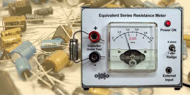
Test Capacitors Using ESR Meter
ESR meters measure the internal resistance of a capacitor, and elevated ESR values can indicate a faulty capacitor. Here’s a step-by-step guide on how to test a capacitor using an ESR meter:
Note: Ensure that the capacitor is discharged before testing to avoid any electrical hazards.
1. Select the Right ESR Meter
Use an ESR meter that is suitable for the type and value of the capacitor you want to test. ESR meters are especially useful for electrolytic capacitors commonly found in power supplies and audio equipment.
2. Identify the Capacitor
Locate the capacitor within the circuit that you want to test. Identify its terminals, noting the polarity if it’s an electrolytic capacitor.
3. Disconnect Power
Ensure that the circuit is de-energized and disconnected from the power source to prevent electrical shock or damage.
4. Discharge the Capacitor
To ensure the capacitor holds no residual charge, short-circuit its terminals with a resistor or an insulated screwdriver. This step is crucial for safety.
5. Set Up the ESR Meter
- Turn on the ESR meter and set it to the appropriate range or mode for the capacitor you are testing. Some ESR meters have auto-ranging capabilities.
- Ensure the meter is calibrated and ready to take measurements.
6. Connect the ESR Meter:
- Connect the ESR meter’s test leads to the capacitor terminals, observing the correct polarity if applicable (negative lead to the negative terminal, positive lead to the positive terminal).
- Be sure to make secure and good-quality connections to get accurate readings.
7. Take the Measurement
- Press the ESR meter’s measurement button or trigger to start the measurement process.
- The meter will display the ESR value in ohms (Ω). This value represents the Equivalent Series Resistance of the capacitor.
- Note the ESR reading.
8. The Result
- A low ESR reading (close to the capacitor’s specified value) indicates that the capacitor’s internal resistance is within the normal range, suggesting a healthy capacitor.
- A significantly elevated ESR reading, well above the manufacturer’s specified value, suggests a faulty capacitor. The extent of deviation from the expected ESR value can indicate the severity of the problem.
Capacitor Testing by Shorting the Leads

- At first, the capacitor must be disconnected from the circuit board and then it should be discharged completely.
- Next, the leads of the capacitor must be connected to the supply terminal.
- After that, the power supply should be switched on for a very short period of time (usually 1 second to 5 seconds) and then it must be switched off. The Capacitor leads; then have to be disconnected from the power supply.
- The terminals of the Capacitor should be shorted by using metal contact. This step must be done by taking proper insulating measures.
- The condition of the Capacitor can be determined by the spark from the Capacitor. For a Capacitor in good condition, the spark is large and strong. For a bad Capacitor, the spark is small and weak.
How to Test Capacitor without a Meter?
If you don’t have a multimeter, you can still perform some basic tests such as:
1. Visual Inspection
Start by examining the physical condition of the capacitor:
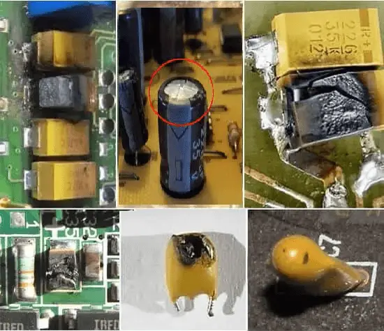
- Look for signs of physical damage, such as cracks, bulges, or leaking electrolyte (a brownish or oily substance).
- Check for any burnt or discolored marks on the capacitor body.
- Sniff for any unusual odors, as a burnt or overheated capacitor can emit a distinct smell.
If you observe any of these visual anomalies, it’s a strong indication that the capacitor is likely bad and needs replacement.
2. Comparative Test for Capacitors
If you have a similar capacitor with a known capacitance value (either from the same circuit or a spare part), you can compare the suspected capacitor with the known good one. Here’s how:
- Disconnect the suspected capacitor from the circuit.
- Disconnect any wires or leads connected to the capacitor terminals.
- Swap the known good capacitor with the suspected one in the circuit.
- Power up the circuit and observe its behavior. If the circuit now functions correctly with the known good capacitor, it suggests that the suspected capacitor may be faulty.
3. Simple Circuit Test for Capacitors
Another way to test a capacitor without a meter is to use a simple circuit to check if it’s storing and releasing charge. Here’s a basic setup:
- Disconnect the capacitor from the circuit.
- Connect the capacitor in series with an LED (Light Emitting Diode).
- Connect one end of the capacitor to the positive lead of the LED, and the other end to the negative lead of the LED.
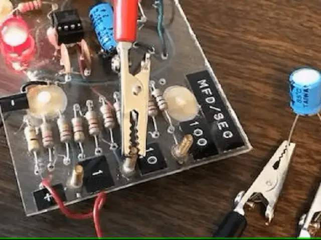
- If the LED lights up briefly when you connect the capacitor to a power source (e.g., a battery), it indicates that the capacitor is storing and discharging energy. However, this test won’t provide information about the capacitor’s capacitance value; it only tells you if it’s functioning to some extent.
How To Test Capacitor in Circuit
Testing a capacitor in-circuit can be challenging because it’s influenced by other components and connections within the circuit. However, it’s possible to assess a capacitor’s functionality and health while it’s still connected to a circuit. Here’s a step-by-step guide on how to test a capacitor in-circuit:
Note: Ensure that the circuit is de-energized and disconnected from the power source before attempting to test the capacitor.
1. Identify the Capacitor’s Pins
Locate the capacitor within the circuit and identify its terminals. It’s essential to know which pins are connected to the capacitor so you can measure voltage across it.
2. Safety First
Before proceeding, ensure that the circuit is not powered. Disconnect any power source or batteries and discharge the circuit if necessary.
3. Use an Oscilloscope
Here’s how to do it:
- Connect the oscilloscope probes across the terminals of the capacitor. Ensure the probe polarity is correct.
- Apply a known input signal or voltage to the circuit.
- Observe the waveform displayed on the oscilloscope.
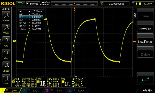
4. Interpret the Waveform
When you apply a signal or voltage to the circuit, the waveform on the oscilloscope will provide valuable information:
- Normal Behavior: In a healthy circuit, a capacitor should charge and discharge smoothly, leading to a well-defined waveform.
- Abnormalities: If the waveform appears distorted, irregular, or exhibits unexpected characteristics, it may indicate a problem with the capacitor. For example, a capacitor with a high internal resistance may cause voltage spikes or distorted waveforms.
5. Compare with Reference
If possible, compare the observed waveform with a known good reference circuit. This can help you identify discrepancies and anomalies in the capacitor’s behavior.
6. Measure Voltage Across the Capacitor
Using a multimeter set to measure voltage (DC or AC, depending on the circuit), you can check the voltage across the capacitor terminals while the circuit is powered. This can provide insights into the capacitor’s charge and discharge characteristics.
- Connect the multimeter probes to the capacitor terminals, ensuring the correct polarity.
- Power up the circuit.
- Observe the voltage reading on the multimeter. A stable and expected voltage reading is a good sign, but significant fluctuations or unexpected values could indicate a problem with the capacitor.
7. Consider Temperature and Environmental Factors
Sometimes, capacitors can behave differently under varying temperature conditions or in specific environments. If your circuit operates in extreme conditions, consider how temperature and environmental factors might affect the capacitor’s performance.
8. Consult Circuit Schematics and Documentation
If you have access to circuit schematics or documentation, review them for insights into the expected behavior of the capacitor in the specific circuit. This can help you identify normal and abnormal operating conditions.
Also Read:
What is Voltage Stabilizer - Why we need it, How it works, Types and Applications
How to Choose Battery - Method & Short / Long Term Power Requirements
Microcontroller - Classification, Architecture, Application, Advantage
I don’t think the title of your article matches the content lol. Just kidding, mainly because I had some doubts after reading the article.
3z8788
yjgvrm
Your style is so unique compared to many other people. Thank you for publishing when you have the opportunity,Guess I will just make this bookmarked.2
Simply wish to say your article is as surprising. The clearness in your post is just spectacular and i can assume you’re an expert on this subject. Fine with your permission let me to grab your RSS feed to keep updated with forthcoming post. Thanks a million and please carry on the enjoyable work.
Wow! Thank you! I always needed to write on my blog something like that. Can I include a fragment of your post to my site?
Its great as your other content : D, thanks for posting. “Age is a function of mind over matter if you don’t mind, it doesn’t matter.” by Leroy Robert Satchel Paige.
I truly appreciate this post. I have been looking everywhere for this! Thank goodness I found it on Bing. You’ve made my day! Thank you again!
I found your weblog site on google and check a number of of your early posts. Proceed to maintain up the excellent operate. I simply further up your RSS feed to my MSN News Reader. Searching for ahead to reading extra from you in a while!…
Thank you for your sharing. I am worried that I lack creative ideas. It is your article that makes me full of hope. Thank you. But, I have a question, can you help me?
Hey, you used to write magnificent, but the last few posts have been kinda boring… I miss your tremendous writings. Past several posts are just a little out of track! come on!
You could definitely see your enthusiasm in the work you write. The world hopes for even more passionate writers like you who are not afraid to say how they believe. Always go after your heart.
I carry on listening to the reports talk about getting boundless online grant applications so I have been looking around for the finest site to get one. Could you tell me please, where could i get some?
Enjoyed reading this
you have an incredible blog right here! would you wish to make some invite posts on my weblog?
Quality content
Wow that was odd. I just wrote an very long comment but after I clicked submit my comment didn’t show up. Grrrr… well I’m not writing all that over again. Regardless, just wanted to say superb blog!
Some genuinely quality content on this internet site, bookmarked.
Appreciate it for helping out, good information.
I’ve been browsing on-line greater than three hours nowadays, but I never discovered any interesting article like yours. It’s lovely worth sufficient for me. In my view, if all web owners and bloggers made good content as you probably did, the internet will probably be a lot more useful than ever before. “Where facts are few, experts are many.” by Donald R. Gannon.
Thanks for sharing excellent informations. Your web-site is very cool. I am impressed by the details that you?¦ve on this site. It reveals how nicely you perceive this subject. Bookmarked this web page, will come back for more articles. You, my pal, ROCK! I found just the information I already searched everywhere and just couldn’t come across. What a great website.
Saved as a favorite, I really like your blog!
hi!,I really like your writing so so much! share we keep up a correspondence extra about your article on AOL? I need an expert on this area to unravel my problem. Maybe that’s you! Taking a look ahead to see you.
hello there and thank you for your information – I’ve certainly picked up anything new from right here. I did however expertise a few technical points using this site, as I experienced to reload the web site many times previous to I could get it to load correctly. I had been wondering if your web host is OK? Not that I am complaining, but slow loading instances times will often affect your placement in google and can damage your high quality score if advertising and marketing with Adwords. Well I am adding this RSS to my email and can look out for much more of your respective interesting content. Ensure that you update this again soon..
Can you be more specific about the content of your article? After reading it, I still have some doubts. Hope you can help me.
This is really interesting, You are a very skilled blogger. I’ve joined your rss feed and look forward to seeking more of your magnificent post. Also, I’ve shared your website in my social networks!
I was very pleased to find this web-site.I wanted to thanks for your time for this wonderful read!! I definitely enjoying every little bit of it and I have you bookmarked to check out new stuff you blog post.
Hi there! I just wanted to ask if you ever have any trouble with hackers? My last blog (wordpress) was hacked and I ended up losing a few months of hard work due to no backup. Do you have any methods to protect against hackers?
One on one saves, goalkeeper shot stopping in isolated situations
wawanesa car insurance quote [url=https://otvetnow.ru]https://otvetnow.ru[/url] condominium insurance coverage
Crypto Pokies Australia Real Money Quiet Wins Building Fortunes
Good day very nice website!! Man .. Excellent .. Amazing .. I’ll bookmark your web site and take the feeds also…I am happy to find so many helpful info right here in the put up, we want work out more techniques on this regard, thanks for sharing. . . . . .
Good day! This is kind of off topic but I need some guidance from an established blog. Is it very difficult to set up your own blog? I’m not very techincal but I can figure things out pretty quick. I’m thinking about creating my own but I’m not sure where to begin. Do you have any tips or suggestions? Appreciate it
When I originally commented I clicked the “Notify me when new comments are added” checkbox and now each time a comment is added I get several e-mails with the same comment. Is there any way you can remove people from that service? Cheers!
2ktk6m
I want reading through and I believe this website got some truly utilitarian stuff on it! .
There are some interesting time limits on this article however I don’t know if I see all of them heart to heart. There may be some validity however I’ll take maintain opinion till I look into it further. Good article , thanks and we want more! Added to FeedBurner as nicely
wsltn8
I have not checked in here for a while as I thought it was getting boring, but the last few posts are good quality so I guess I’ll add you back to my daily bloglist. You deserve it my friend 🙂
You actually make it appear so easy with your presentation however I in finding this topic to be really one thing that I believe I’d by no means understand. It kind of feels too complex and extremely vast for me. I am having a look forward on your subsequent put up, I will attempt to get the hang of it!
I am thankful that I observed this blog, precisely the right information that I was searching for! .
I as well conceive thus, perfectly indited post! .