
Filters are electronic circuits that remove any unwanted components or features from a signal. In simple words, you can understand it as the circuit rejects certain band of frequencies and allows others to pass through. They are widely used in Instrumentation, Electronics and Communication Systems especially in Signal and Image processing systems. This post will give you a brief idea about what are Filters, its classification, characteristics, types, applications, advantages and disadvantages.
What are FiltersÂ
Filters are essential building blocks of any Electronic and Communication Systems that alter the amplitude and/or phase characteristics of a signal with respect to frequency. Filter is basically linear circuit that helps to remove unwanted components such as Noise, Interference and Distortion from the input signal. Ideally Filter alters the relative amplitudes of the various frequency components and the phase characteristics and its ‘Gain’Â depends entirely on the signal frequency.

Fig. 1 – Introduction to Filter
A Filter is defined by their frequency-domain effects on signals, which is often described mathematically in terms of its Transfer function and it is expressed in the ratio of the Laplace Transforms of its Output and Input signals.
The voltage transfer function H(s) of a Filter Circuit is written as:

Where,
- VIN(s) = Input Signal
- VOUT(s) = Output Signal
- S = Complex Frequency Variable.
By replacing the variable ‘S’ in the above equation with jὠ, where j is equal to ![]() and ὠis the radian frequency (2ᴨf), we can find the filter’s effect on the Magnitude and Phase of the Input signal.
and ὠis the radian frequency (2ᴨf), we can find the filter’s effect on the Magnitude and Phase of the Input signal.
The Magnitude is found by taking the absolute value of equation (1):


Fig. 2 – Block Diagram of Filter Circuit
Classification of Filters
Filter is mainly classified into two types:
- Active Filter
- Passive Filter
Active Filters
Filter Circuit which consists of active components like Transistors and Op-amps in addition to Resistors and Capacitors is called as Active Filter.
Passive Filters
Filter circuit which consists of passive components such as Resistors, Capacitors and Inductors is called as Passive Filter. The operating frequency range of the filter banks on the components used to build the circuit. Hence the filter can be further categorized based on the operating frequency of a particular circuit. They are:
- Low Pass Filter
- High Pass Filter
- Band Pass Filter
- Band Stop Filter
- All Pass Filter
Low Pass Filters
It is a type of Filter which attenuates all the frequencies above the cut-off frequencies. It provides a constant output (gain) from zero to cut-off frequency.
 Actual (b) Ideal")
Fig. 3 – Low Pass Filter Characteristics (a) Actual (b) Ideal
High Pass Filters
It is a type of Filter which attenuates all the frequencies below the cut-off frequencies. It provides a constant output (gain) above the cut-off frequency.
 Actual (b) Ideal")
Fig. 4 – High Pass Filter Characteristics (a) Actual (b) Ideal
Know More About High Pass Filter - Types, Applications, Advantages & Disadvantages
Band Pass Filters
It is a type of filter which allows specific Band of frequencies to pass through and all other frequencies outside the band are attenuated.

Fig. 5 – Band Pass Filter Characteristics
Band Stop Filters
Specific Band of frequencies gets rejected and allows passing of frequencies outside the Band.
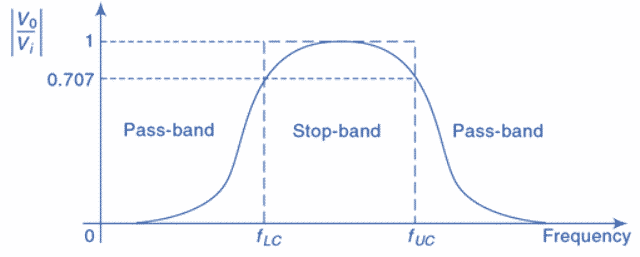
Fig. 6 – Band Stop Filter Characteristics
All Pass Filters
It is a type of filter which passes all frequencies equally. It is also known as Phase-Shift filter, time-delay filter as the output voltage shifts in phase with respect to input voltage but they are equal in magnitude.

Fig. 7 – All Pass Filter Characteristics
Applications of Filters
The applications include:
- Filter Circuits are used to eliminate background Noise
- They are used in Radio tuning to a specific frequency
- Used in Pre-amplification, Equalization, Tone Control in Audio Systems
- They are also used in Signal Processing Circuits and Data Conversion
- Filter Circuits are extensively used in Medical Electronic Systems
Advantages of Filters
The advantages are:
- They are economical or cost-effective
- Unlike passive filter circuits, Active Filter Circuits require power supply
Disadvantages of Filters
The disadvantages are:
- Circuits are bulky
- Limited Bandwidth
- Increased sensitivity to variation in circuit parameters
Also Read:
Class C Amplifier - Working Principle, Applications, Advantages & Disadvantages
Waveguide – Classification, Modes, How it Works, Application, Advantage
Pulse Width Modulation (PWM) – Generation, Applications and Advantages