
Arithmetic Subtraction of binary digits is performed using Subtractor Circuit. This post will discuss about what is Subtractor Circuit, it’s types (Half Subtractor and Full Subtractor), its Applications, Advantages and Disadvantages.
What is Subtractor Circuit
Subtractor Circuit is a combinational logic circuit that performs subtraction on binary numbers. As the digits involved in Binary Notation are 0 and 1, subtraction of ‘0’ from a ‘0’ or ‘1’ does not change the result. ‘1’ subtracted from ‘1’ results in ‘0’. Subtracting ‘1’ from ‘0’ requires borrow.
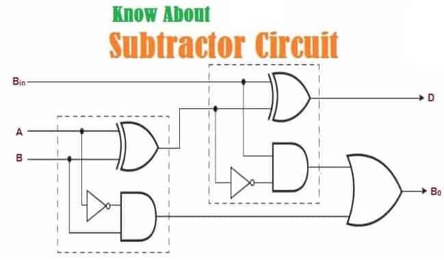
Fig. 1 – Introduction to Subtractor Circuit
Fig. 2 shows 2-bit Subtractor which has 2 inputs A, B. This circuit produces Difference and Borrow bit. The circuit consists of an Adder with inverters placed between each data input and Bin (Borrow) input of the previous stage of Full Adder.
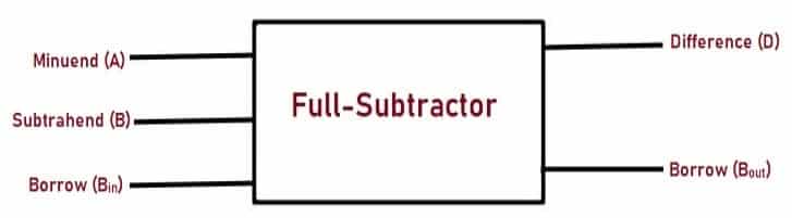
Fig. 2 – Block Diagram of Full-Subtractor Circuit
Types of Subtractor Circuit
There are two types of subtractor circuit. They are:
- Half Subtractor
- Full Subtractor
Half Subtractor
Two single bit binary numbers can be subtracted by using Half Subtractor circuit. This circuit needs two binary inputs ‘A’ and ‘B’ to produce two binary outputs ‘D’ and ‘b’. ‘A’ bit is Minuend, ‘b’ bit is Subtrahend. The output bit ‘D’ is the difference bit and ‘b’ is Borrow bit.
Let us create Truth Table for different values of input A and B.

Fig. 3 – Truth Table Representation of Half-SubtractorÂ
For the above Truth Table entries, K-Maps is drawn to determine the Boolean expression.
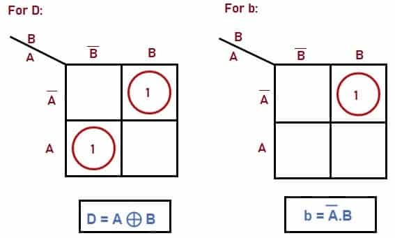
Fig. 4 – K-Map Representation of Half-SubtractorÂ
D is an EX-OR gate and Borrow (b) is ‘And’ gate with complemented input A. When the output of half-adder and half- subtractor is compared, the Boolean expressions for SUM and Difference outputs are the same.
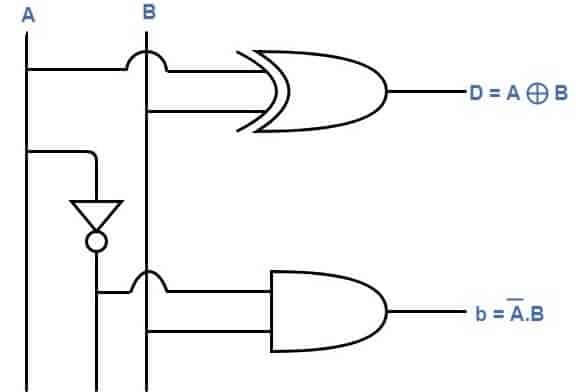
Fig. 5 – Logic Diagram of Half SubtractorÂ
Full Subtractor
Full Subtractor logic circuit performs subtraction on three-bit binary numbers. It is implemented by using two Half Subtractor circuits along with OR gate. This circuit has three inputs A, B and Bin. Bin is the borrow-in bit from the previous stage. It produces two output bits D and Bout.
D is the Difference bit and Bout is the borrow out bit. Bout indicates that the minuend bit requires borrow 1 from the consequent or subsequent minuend bit. Let us create Truth Table for different values of inputs A, B, Bin.
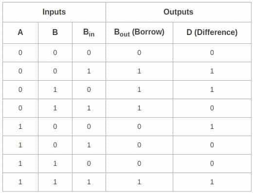
Fig. 6 – Truth Table Representation of Full SubtractorÂ
For the above Truth Table entries, K-Maps is drawn to determine the Boolean expression.

Fig. 7 – K-Map Representation of Full-SubtractorÂ
When this circuit is compared with Full Adder, we observe that Difference output is same as the Sum Output. The implementation of the circuit is done using 1 XOR gate, 3 AND gates, 1 NOT gate and 1 OR gate as shown below:
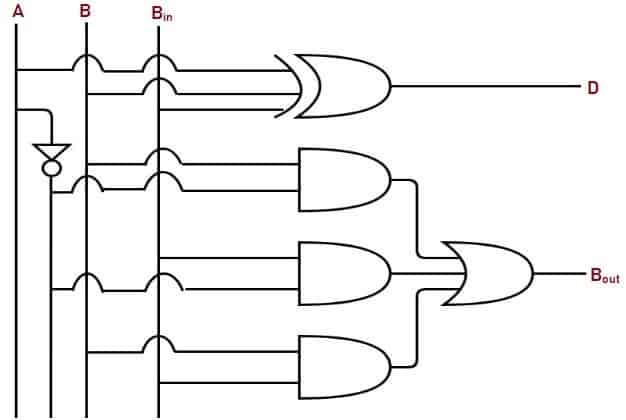
Fig. 8 – Logic Diagram of Full SubtractorÂ
How does Subtractor Circuit Work
The circuit is assembled as per the circuit diagram. DIP switches and resistors are connected to the inputs and LED’s are connected to the outputs. Hexadecimal Display is also connected to Output.
Power of 5V is applied at Vcc. Mode and Operation is selected according to the application. Here Mode=Operation= 1. The logic state of the outputs indicated by LED’s are noted for each input combination. Logic High = 1 = LED glows and Logic Low = 0 = LED is off. The results obtained are verified with the entries of the Truth-Table.
Fig. 9 shows simple ALU (subtractor) that performs subtraction result of A – B and the subtraction of two 4-bit numbers will not exceed 8 bits. The result is displayed in Binary by LED’s and in Hex by Seven Segment Display.

Fig. 9 – Subtraction Operation on ALU
Applications of Subtractor Circuit
The applications include:
- It is used in ALU (Arithmetic Logic Unit) and CPU (Central Processing Unit)
- They are widely used in electronic calculators and in devices like timers and program counters.
- They are also used in Digital Signal Processing.
Advantages of Subtractor Circuit
The advantages are:
- It is simple to design and implement.
- Power deduction in Digital Signal Processing.
- Computational tasks can be carried out at high speed.
Disadvantages of Subtractor Circuit
The disadvantages are:
- In case of half subtractor, there is no provision for accepting Borrow as input from the previous stage.
- The speed of the subtractor is limited by the longest delay through the circuit.
Also Read:
Logic Gates - Types, Working Principle, Application, Advantage
Karnaugh Map (K-Map) - Minterm, Maxterm, Simplification & Applications
Logic Gates – Types, Working Principle, Application, Advantage
it is really complex for a year 9 student,please try making it more easy and understandable.
THANKS.
I appreciate, lead to I found just what I was having a look for. You have ended my 4 day long hunt! God Bless you man. Have a nice day. Bye
Plunge into the expansive universe of EVE Online. Find your fleet today. Fight alongside hundreds of thousands of players worldwide. [url=https://www.eveonline.com/signup?invc=46758c20-63e3-4816-aa0e-f91cff26ade4]Start playing for free[/url]
Plunge into the vast universe of EVE Online. Forge your empire today. Explore alongside millions of players worldwide. [url=https://www.eveonline.com/signup?invc=46758c20-63e3-4816-aa0e-f91cff26ade4]Join now[/url]
Respect to post author, some wonderful entropy.
casr7i
Hmm is anyone else having problems with the pictures on this blog loading? I’m trying to find out if its a problem on my end or if it’s the blog. Any suggestions would be greatly appreciated.
Your article helped me a lot, is there any more related content? Thanks!
Świetny artykuł, dzięki za info. Temat ciekawy i świetnie pozwalający rozwijać wyobraźnie.
Bardzo chciałbym założyć bloga, ale… Nie jestem pewien, jaki rodzaj blogów ma największy ruch? Jakie blogi przeglądasz? Najczęściej przeglądam blogi fotograficzne, kulinarne i blogi modowe. i Właśnie twego bloga dopiero zaczynam obserwować ps. Dobrze, że jest aktywne RSS.
656j5h
Can you be more specific about the content of your article? After reading it, I still have some doubts. Hope you can help me.
With havin so much written content do you ever run into any issues of plagorism or copyright infringement? My site has a lot of exclusive content I’ve either authored myself or outsourced but it appears a lot of it is popping it up all over the internet without my authorization. Do you know any ways to help protect against content from being ripped off? I’d definitely appreciate it.
Great post. I am facing a couple of these problems.
I’ve been absent for a while, but now I remember why I used to love this website. Thank you, I’ll try and check back more frequently. How frequently you update your site?